

Building a new computer feels like a daunting task: What if I mess it up? Install something incorrectly? Can’t make something work? Break everything? I know it seems scary if you haven’t done it before, but I promised it’s really just like a grown up set of Legos that becomes something useful. There are thousands of online sources for information about computer building, and in many circles, its like a techie right-of-passage. You get a certain amount of nerd-clout if you’ve built your own computer.
So now that you’ve read through Step 1 : Choosing your Parts, its time to learn how it all goes together.
Crucial Notes
Throughout this process, it’s VERY important that you prevent a buildup of static electricity from accidentally frying your parts. Try not to stand on carpet, and every few minutes, make sure to touch the bare metal on the case to discharge any build up. Many computer builders will recommend wearing an anti-static wrist strap to do this for you, but I usually don’t. But this is your warning. It’s a thing for a reason.How to Build
Since there are SO many tutorials for this kind of thing on the internet, I’m going to keep mine simple, step-by-step, and generic. For each step, you’ll need to take what I’m talking about and apply it to your specific scenario. For instance, when we talk about installing the CPU into the motherboard, there are many various types of CPU shape and size and socket and chipsets, and it’s easy to get bogged down in details about every single thing. Look at the user manual that came with your specific one and do that thing it says to do.
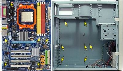
Step 1: Build the “Platform”
This is installing your CPU, CPU Cooler, and RAM into the motherboard. Carefully, gripping only from the sides, take out your CPU from the box. Be incredibly careful not to damage the pins on the bottom, as these must line up exactly with the motherboard slots. Usually, there will be a corner thats a different shape, or an arrow somewhere that shows you how it aligns. Lift the locking lever on the side of the slot on the motherboard, set the CPU down carefully, and lock the lever again.
Apply a small amount of thermal grease on top of the CPU, and then spread it around a bit. Mount the CPU cooler/fan assembly on top. Some of these will click into place and some have little metal levers that attach to both sides. Lock these down, and then plug in the fan that’s usually on top of the heatsink. There should be a 3 or 4 pin spot somewhere next to the CPU slot. Check your manual. It will have a picture of where it is, but it should be easy to spot. It should also have “CPUFAN” or something like that printed nearby. If you need more detail, head to this PCWorld article on Installing a CPU cooler.
Next, grab your RAM sticks and let’s install these. Read through your motherboard manual real quick to see exactly which slots to put your sticks in. It does matter, and it does differ depending on your motherboard. You will normally have 4 slots for RAM, and if you have 4 sticks, it won’t matter. But if you just have 2, then maybe you will use slots 1&2, or slots 1&3, or slots 2&4, so make sure you read. It also matters if you just have 1 stick. There is only one way to push RAM into the slot, so make sure the slot key lines up with the middle of the RAM that has a hole for the slot key to slide up into. Push down until the edge plastic clips pop into place.
Step 2: Power Supply (PSU)
Now that the platform is built, we can start putting things into the case. Lay the case down on it’s side up on a table, and remove the work side panel. (You can usually remove both sides from the case, so go ahead and do this. One side will allow you to put components in, the other side will allow you to do cable routing.)
Start with the power supply. This is the big, bulky box that is hard to get in there anyway, so go ahead and install it before anything else to make it easier on yourself. It should just slide into the spot for it, always in the back, but sometimes up top and sometimes down at the bottom. Switch goes out, cables go in. There will be screw holes on the back through the rear of the case. Go ahead and screw it in to secure it as we will be rotating the case all around.
Step 3: Install motherboard platform.
The most crucial step is to identify which size motherboard you have (ATX, mini-ATX, micro-ATX, etc.) and pre-screw in the small brass standoffs into the back of the case. There will be small labels next to each potential screw point that says “ATX” or whatever, and fill all those holes with a standoff. The standoffs prevent the back of the motherboard from touching the case. This is more important than you think. When I built my first computer (around 14 years old), I didn’t know about this drastically important step. I built the whole computer without these standoffs and the first time I turned it on, the back of the motherboard shorted to the case, everything caught on fire and sparked, and the motherboard was instantly toast. It took a family friend helping me with the RMA to get a new one under warranty. It was a mess. So put the standoffs in.
Example of ATX standoff locations
Do as I say....
When I built my first computer (around 14 years old), I didn’t know about this drastically important step. I built the whole computer without these standoffs and the first time I turned it on, the back of the motherboard shorted to the case, everything caught on fire and sparked, and the motherboard was instantly toast. It took a family friend helping me with the RMA to get a new one under warranty. It was a mess. So put the standoffs in.Next, go ahead and put in the I/O shield. It’s the metal plate that came with your motherboard that has slots for the motherboard in the case that say what each slot is. It makes the computer look cleaner (vs having a big hole back there) and tightens up airflow. Install this before putting the motherboard in.
Set the motherboard down on the standoffs, making sure you can see them all through the pre-drilled screw holes on the motherboard, and then begin to put screws in them through the motherboard, securing it to the case.
Step 4: Install the PCIe Cards
Technically, with a hard drive, your computer could be up and running. But to make your computer more useful, we want to install the PCIe cards. These are all of the extra functionality cards that slide into those long slots near the back side of the motherboard, and give you ports for things like monitors and USB devices that stick out the back. A motherboard generally has basic USB slots and a spot to plug in a monitor to the onboard graphics processor, and maaaaybe an ethernet plug, but we want USB3.0, a dedicated GPU powered monitor for gaming, and a wifi card.
It does matter which one you plug stuff into, so check to see how many “lanes” each slot can support. Generally, you want to put your GPU card as close to the CPU as you can. This is commonly reserved as a GPU capable slot and has the biggest throughput of all the slots. Then, just go down from the top to the bottom and install your cards. They should push down into the slot firmly and then be secured in with a single screw on the inside of the case back where the card lines up with the rear slot. You may have to punch out some metal slot placeholders to get room for the card to stick out the back. These are just aesthetic and you can easily remove them to make room.
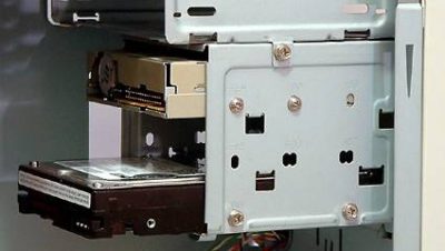
Example Hard Drive Cage: 2 HDD drives installed with space in between them for airflow.
Step 5 : Install your Hard Drives
There are generally two methods, depending on your case, for installing HDD and SSD’s. There will either be a hard drive cage, that has sliding trays for each drive, or “Drive Bays” where you just have a dedicated slot and you screw the drive in to the side of the case. Make sure you use screws on both sides to properly level and support the drive. Don’t just support it on one side. If you have room, leave some space between the drives to allow for better airflow. Use drive bays 1 & 3 if you have 2 hard drives, for example.
Each hard drive will have two cables: a power cable from the PSU, and an information SATA cable, to the motherboard. The power cable is straight forward. There is generally just one cord that will fit the plug on the back of the hard drive (its a standard shape, so pick the one that fits). The SATA cable is an L shaped plug that goes into a SATA slot on the motherboard. My particular motherboard has 6 SATA slots, but I only have 3 SATA drives, (one SSD and two HDDs), so I use slots 1,2, and 3.
Step 6: Install your Optical Drives
If you have one, or two, pull out the plastic front cover on the 5.25″ drive bay and slide the drive in the front of the case. Secure with screws and connect your power and data cables just like the hard drives. If its a modern drive, it will be the same type of cables and plug into the next SATA spot on the motherboard. In my case, SATA4.
Step 7 : Plug everything in
Most every part in the build has a power cable that needs to be hooked up, and this is probably the most tedious part of the build. But luckily, each plug only fits one way, so that’s nice.
Cable Management
Hardcore computer builders get very specific about how they route cables, but the “benefits” to a clean case are vague and unconvincing to me. I do recommend, though, that you at least give it a shot at making the case tidier. You definitely want to keep cables from getting caught up in a fan or pulled out accidentally, but there are those who argue that the cables can block airflow (enough to create a significant temperature difference) and I’m just not on that bandwagon. If you’re interested in more techniques, check out this guy’s youtube tutorial series.Here are the cords you need to plug in:
A 24-pin motherboard cable. This is the big one. It goes in the big slot on your motherboard.
A 4 (or 6) pin secondary motherboard cable. This will probably be nearby the 24 pin one. I’m not sure why they are separate, but almost all modern systems will have both of these.
6 pin PCI cables. If you have a dedicated GPU, you likely need one of these plugged into it. But not always. Just look at the manual for the card.
SATA Power and Data Cables: We briefly covered this above, but each drive should have one of both of these cables. Power and Data.
Molex Power Cables: These are an older standardized plug (its a bulkier 4 pin plug) that used to be used for drives (vs SATA now), but generally all it’s used for these days are case fans and extra USB drives.
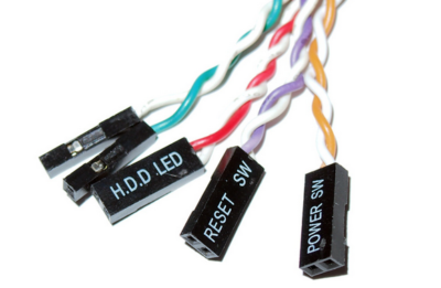
An example of what front panel plugs look like. Make sure to get all of them.
Smaller Case Fans: There are some smaller fans, similar to the CPU heatsink fan, that won’t use the larger molex, but instead have small 3 or 4 pin connectors directly attached to the fans, right out of the box, that will plug directly into the motherboard (not the PSU). Look for pin groupings that say “CPU_FAN” or “SYS1_FAN” or “CASE_FAN”. If your fan has 3 pins, it’ll run, but if it has 4, you’ll be able to control fan speed with software programs based on factors you can setup. This is fun, but generally an extra feature, so don’t worry about it if you don’t have this.
Front Panel Audio/USB/Firewire Connectors: To me, these are the bane of my PC building existence, because they are tiny, but if you just simply read the manual of the motherboard (there’s a theme here), you’ll find a picture that shows you how they fit and in what order. They will be labeled POWERSW, RESETSW, HDD LED, etc.